
Academic Editor: Bernard Belhassen
Catheter ablation is a well-established treatment option for patients with ventricular arrhythmias. Recent advances in various imaging modalities, including three-dimensional electroanatomic mapping systems, magnetic resonance imaging, transesophageal and intracardiac echocardiography (ICE) have been adopted in catheter ablation of ventricular arrhythmias improving procedural outcome and safety. ICE is an imaging tool which provides real-time visualization of anatomical structures of the heart, facilitating catheter manipulation and navigation during ablation procedures. In this review we aim to highlight the benefits of ICE use in catheter ablation of ventricular arrhythmias and to describe practical techniques for visualization of cardiac structures with ICE during ventricular tachycardia ablations.
Catheter ablation is a well-established treatment option for patients with ventricular arrhythmias (VAs). Catheter ablation is recommended in patients with idiopathic VAs and in those with structural heart disease when antiarrhythmic medications are ineffective, not tolerated, or not desired by the patient [1]. Although the main tools for catheter navigation used in ventricular tachycardia (VT) ablation are fluoroscopy and electroanatomic mapping, intracardiac echocardiography (ICE) is increasingly incorporated in VT ablation practice since it enables real-time visualization of the ablation catheter and specific anatomical structures of the heart, thus improving procedural efficacy and safety.
Clinical studies have shown that the use of ICE in ablation of cardiac arrhythmias results in significantly improved procedural outcome, reduced risk of complications, radiation exposure, redo ablations and readmissions [2, 3, 4]. A recent meta-analysis, including 19 studies with 2186 patients (with history of either atrial or ventricular arrhythmias), compared procedural outcomes in catheter ablations with vs without ICE use. The authors found that the use of ICE was associated with significantly reduced fluoroscopy time, fluoroscopy dose and procedural time as compared to those performed without ICE. Regarding safety outcome, a nonsignificant decrease in complications was observed in ICE-guided procedures vs those without [2]. Field et al. [3] recently investigated the clinical outcomes of patients with VT history undergoing catheter ablation with versus without the use of ICE. Based on their findings, ICE use was associated with significantly lower readmissions for VT and lower redo VT ablations, while there were no significant differences in all-cause and cardiovascular-related readmissions. A similar study which compared outcomes among patients with ICD/CRT-D who underwent VT ablation with and without the use of ICE found a significantly lower risk of all-cause readmissions, cardiovascular-related readmission and VT-related readmissions in patients undergoing ICE-guided VT ablation [4].
The following two types of ICE systems are available:
(a) Radial ICE uses a mechanical nonsteerable catheter of varying
diameter (6 to 10 F) with a single, rotating crystal element at its tip. Radial
ICE provides a 360
(b) Phased array ICE catheters are 8 or 10 Fr steerable catheters
incorporating a 64-element transducer, which provides a 90
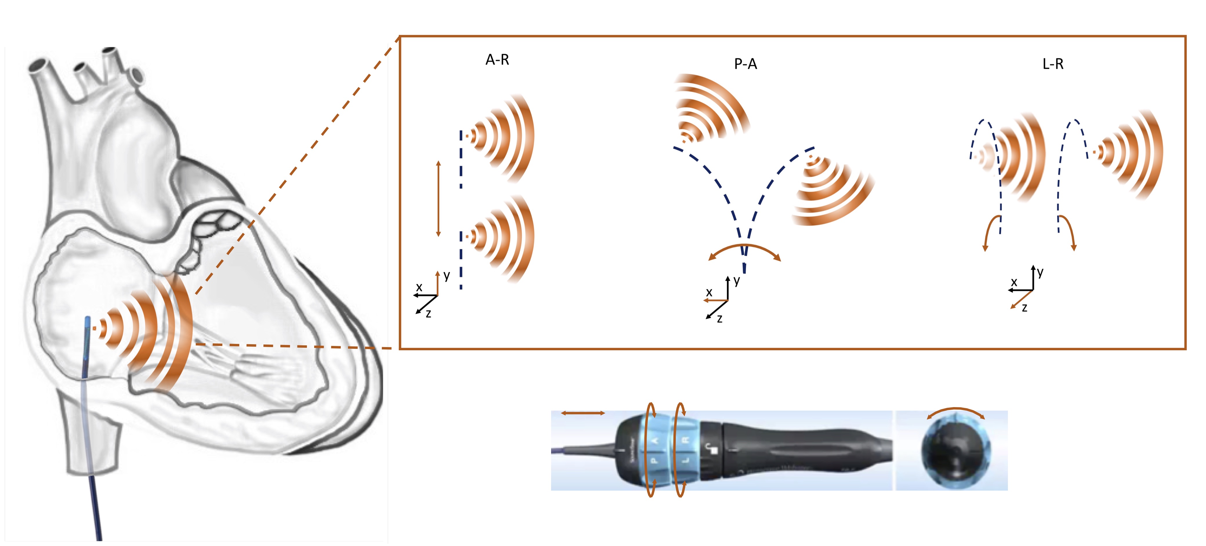 Fig. 1.
Schematic representation of different manipulation options of a phased array ICE catheter. A-R, advancement-retraction; A-P, anterior-posterior; L-R, left-right.
| ICE catheters | ViewFlex Xtra | AcuNav |
| Ultrasound sector | 80 |
90 |
| Transducer | 64 elements | 64 elements |
| Length (cm) | 90 | 90 |
| Size (Fr) | 9 | 8/10 |
| Deflection | 4 directions (A-P/L-R) | 4 directions (A-P/L-R) |
| Echocardiographic capabilities | 2D, PW Doppler, CF | 2D, CW, PW Doppler, CF |
| Tissue penetration (cm) | 18/21 | 16 |
| Locking mechanism | Self-locking | Manual locking |
| Frequency (MHz) | 4.5–8.5 | 3–10 |
| Deflection angle | 160 |
120 |
| A-P, anterior-posterior; L-R, left-right; CW, continuous wave; PW, pulse wave; CF, color flow. | ||
An alternative technology based on ICE and CARTO electroanatomical mapping system is the CARTOSOUND module. A virtual 3D anatomical reconstruction of the cardiac chambers can be created by 2D ultrasound images, using a special 8 or 10 Fr phased-array ICE catheter (SOUNDSTAR, ultrasound catheter, Biosense Webster). With this technology, the cardiac electrophysiologist is able to view ultrasound images in the CARTO system and visualize lesion formation in real time during VT ablation.
ICE-guided catheter ablation of ventricular arrhythmias offers several advantages. Catheter ablation can be performed with significant reduction of radiation exposure or even with zero fluoroscopy [5, 6]. Zero fluoroscopy VT ablation is feasible using a combination of electroanatomic systems and ICE and achieving high acute success and low recurrence rates [5, 7, 8].
The use of ICE requires only a femoral vein access without the need of deep sedation as is the case in transesophageal echocardiography (TEE). Likewise, ICE is superior to TEE as the procedure can be performed by one operator compared to TEE which needs at least two operators.
Furthermore, ICE provides optimal visualization of various anatomical structures, not well recognizable by fluoroscopy such as valves and papillary muscles (PMs), as well as real-time visualization of the ablation catheter in relation to specific anatomic areas. Additionally, it is helpful in identification, delineation and characterization of the substrate for VT in patients with structural heart disease.
Moreover, studies have shown the safety and feasibility of performing VT ablation procedures without use of fluoroscopy. Zero fluoroscopy VT ablation is feasible using a combination of electroanatomic systems and ICE and achieving high acute success and low recurrence rates.
Access to the LV for endocardial mapping and VT ablation can be achieved either by retrograde transaortic or by antegrade transseptal approach. ICE has an invaluable role in gaining safe LA access during transseptal puncture since it enables real-time visualization of the sheath-needle assembly, the fossa tenting and the puncturing the interatrial septum. It should be noted that simultaneous imaging of the septal tenting and the left pulmonary veins confirms optimal positioning of the needle at the interatrial septum, posteriorly to the aorta (Fig. 2). In contrast, visualization of the right inferior pulmonary vein or the left atrial appendage demonstrates a more posterior or anterior view of the septum respectively [5]. These landmarks are important to avoid inadvertent puncture of the left atrial posterior wall or the aorta, especially in high-risk cases with anatomical peculiarities, such as in aneurysmatic or lipomatous septa or in repaired atrial septal defect (Fig. 3). Of note, these landmarks are used for optimal position for atrial fibrillation ablation while a more anterior puncture is favoured for LV access. The use of ICE during transseptal puncture, also excludes the presence of thrombus not only in the left atrial appendage but also at the tip of the sheath or needle (Fig. 3B).
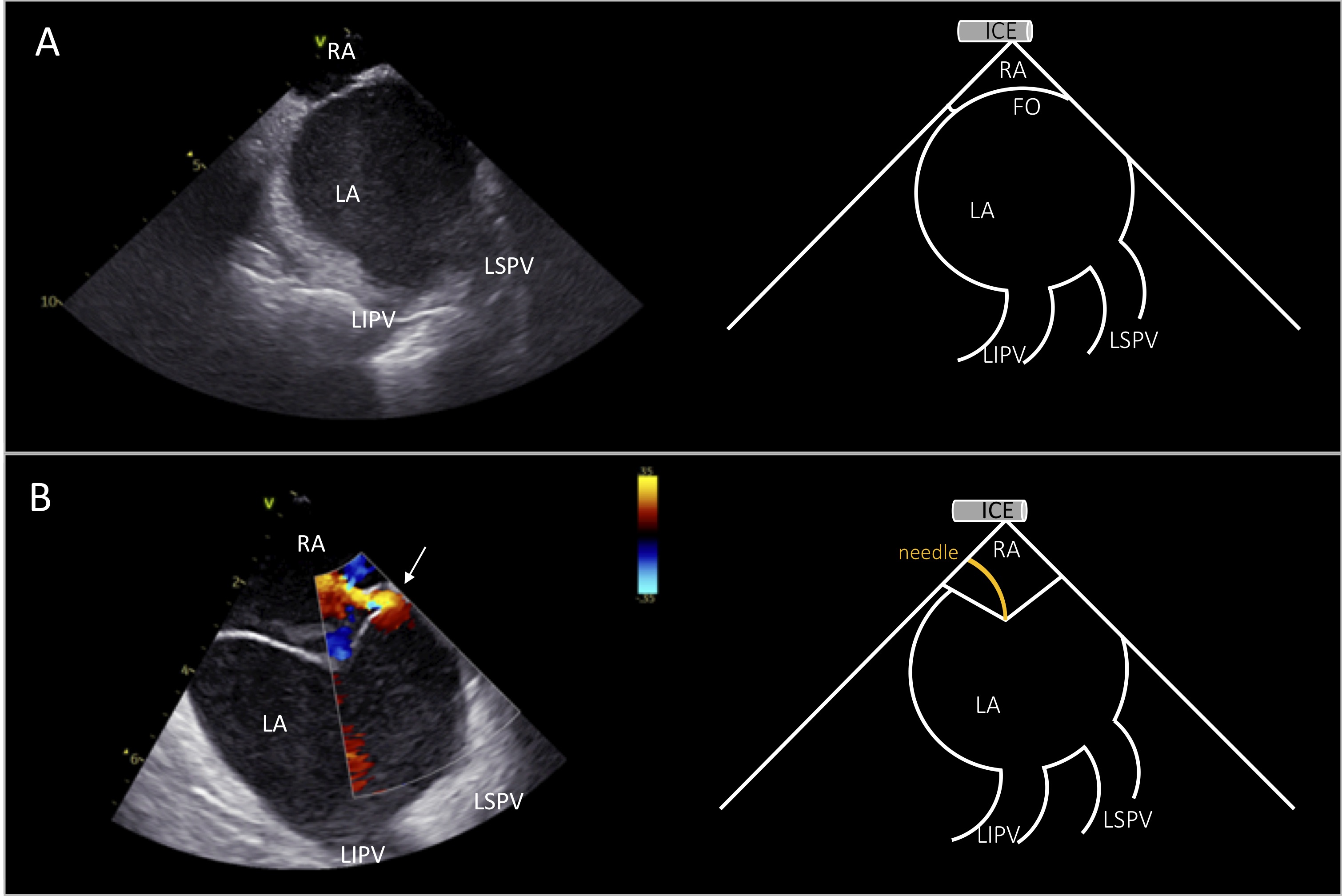 Fig. 2.
ICE view for transseptal puncture. Right atrial view of the interatrial septum during transseptal puncture showing simultaneously the left pulmonary veins (A). Tenting of the fossa ovalis before transseptal puncture. Color doppler shows patent foramen ovale with left-to-right shunt (depicted by white arrow in B). ICE image at the left and schematic representation at the right side of the panels. RA, right atrium; LA, left atrium; LSPV, left superior pulmonary vein; LIPV, left inferior pulmonary vein; FO, fossa ovalis.
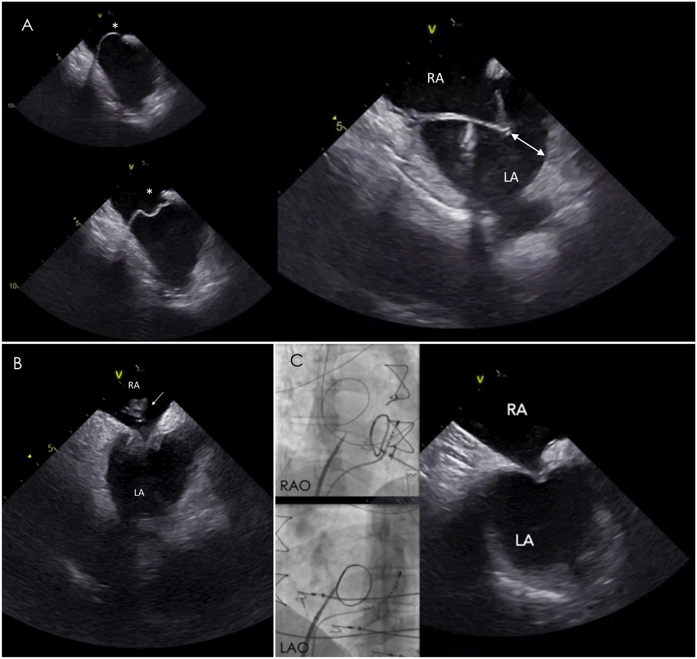 Fig. 3.
Transseptal puncture in challenging septa. (A) In aneurysmatic
septum, ICE is particularly useful to assess the needle direction and the space
(white double headed arrow) between the tented septum and left atrial lateral
wall avoiding inadvertent puncture of the latter. (B) ICE image reveals the
presence of a clot at the tip of the sheath during the transseptal puncture,
despite adequate anticoagulation with activated clotting time
Occurrence of complications during VT ablation is not rare, especially in nonelective procedures and in the presence of underlying structural heart disease. Prompt recognition of procedural complications is crucial for timely management and prevention of adverse patient outcome [9]. Furthermore, early recognition of microbubble formation due to thermal effect can prevent steam pop, while a potential cardiac tamponade can be prevented with prompt detection and management of pericardial effusion [10].
The benefits of ICE-guided VT ablation are summarized in Table 2.
| (a) High-quality imaging due to close proximity of the catheter to the ventricular structures and enhanced visualization of certain anatomical structures, not well recognizable by fluoroscopy: | |
| - aortic and pulmonary cusps | |
| - papillary muscles | |
| - coronary arteries | |
| (b) Safe transseptal puncture | |
| (c) No need of general anesthesia and esophageal intubation | |
| (d) No need of a second operator during the procedure | |
| (e) Early detection of complications: | |
| - left atrial appendage thrombi or thrombi on the sheaths during transseptal puncture | |
| - pericardial effusion | |
| - cardiac tamponade | |
| - microbubble formation preceding steam pop occurence | |
| (f) Identification – delineation – characterization of the substrate for VT | |
| (g) Patient tolerance | |
| (h) Monitoring of catheter-tissue contact | |
Once the ICE catheter is placed in the mid-RA, the study starts from the “home view”, displaying the tricuspid valve (Fig. 4A). From this view, right ventricle (RV), proximal right ventricular outflow tract (RVOT) and part of the aortic valve can be seen. The aortic valve is visualized in the long axis displaying the non coronary cusp (NCC) adjacent to the interatrial septum and the right coronary cusp (RCC), posteriorly to the RVOT. Color Doppler can reveal tricuspid regurgitation and right ventricular systolic pressure should be estimated at the beginning of the procedure especially in patients with LV systolic dysfunction. Slight clockwise rotation, always in neutral position of the catheter, shows the left ventricle (LV), the left ventricular outflow tract (LVOT), the NCC and the left coronary cusp (LCC) (Fig. 4B). Of note, attention should be paid whether the tricuspid valve is visualized or not in order to recognize accurately which coronary cusps are shown. Specifically, with continued clockwise rotation of the ICE catheter, once the tricuspid valve is no more seen in view, it is also not possible to show the RCC which is the more anterior leaflet of the aortic valve. In contrast, further clockwise rotation of the catheter reveals more leftward and posterior structures, including LCC, LV and anterior mitral leaflet (Fig. 4C) [11]. With further clockwise rotation, LV inflow and more clear view of mitral valve can be seen. Optimal visualization of the leaflets of the aortic valve in short axis can be obtained by positioning the ICE catheter in the RV.
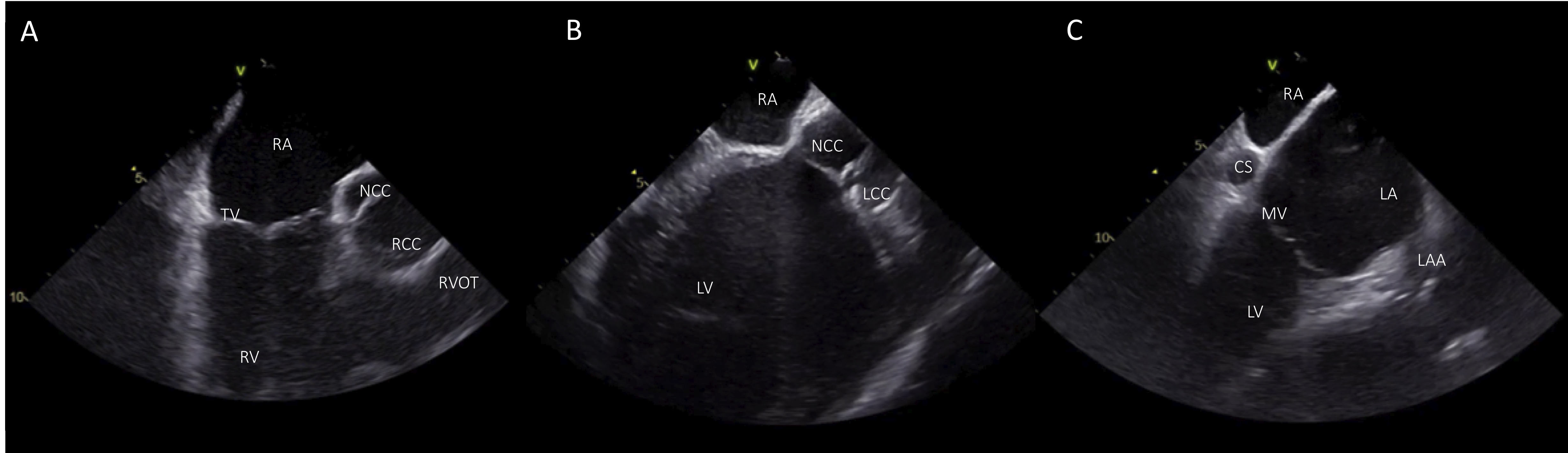 Fig. 4.
Basic views from the RA. (A) Home view with the ICE catheter positioned in the mid-RA. (B) From the home view slight clockwise rotation shows LV, LVOT, and the aortic cusps NCC and LCC. (C) View of the LV with additional clockwise rotation. RA, right atrium; TV, tricuspid valve; RV; right ventricle; NCC, non coronary cusp; RCC, right coronary cusp; RVOT, right ventricular outflow tract; LV, left ventricle; LCC left coronary cusp; CS, coronary cusp; LA, left atrium; LAA, left atrial appendage; MV, mitral valve.
Starting from the home view, the ICE catheter can be positioned in the RV with anterior curve and gentle advancement. Once the transducer is placed into the RV, the curve is slightly released (keeping a modest anterior curve) and the inferior RV, apex and free wall can be seen. From this position, the LV can be visualized with clockwise catheter rotation. During rotation of the catheter, septum is the first segment of the left ventricle that can be seen and further clockwise rotation shows the LV in the long-axis view, the interventricular septum close to the transducer, and the inferior wall with the posteromedial papillary muscle (PPM) more posteriorly (Fig. 5B). This view can also show the LV apex and is more sensitive to detect LV apical clots than transthoracic echocardiography or TEE. Further rotation of the catheter shows the lateral wall, the anterolateral papillary muscle (APM) and the mitral valve (Fig. 5C). With further clockwise rotation (while releasing anterior flex) the catheter is placed on the septal region of the RVOT showing the coronary cusps in a short axis. The more anterior cusp, which is adjacent to the RVOT, is the RCC. The NCC is on the left side of the screen, adjacent to the interatrial septum while the more posterior cusp is the LCC, which is in proximity with left atrial appendage (LAA) (Fig. 5E).
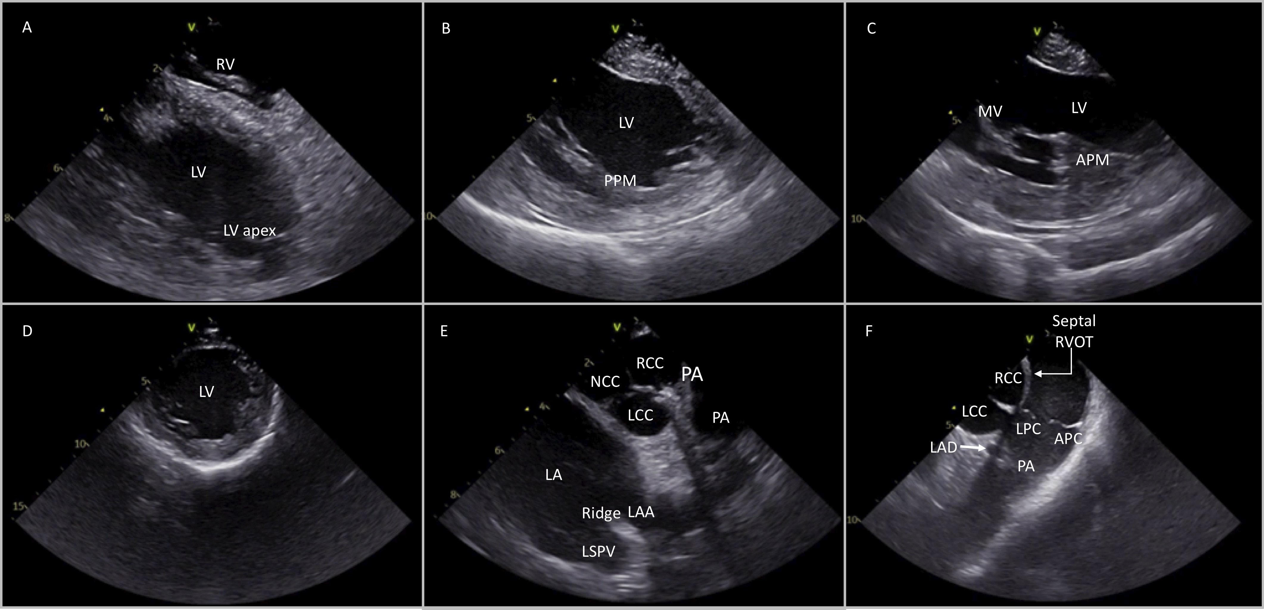 Fig. 5.
Different views of the cardiac structures after placing the ICE catheter into the RV and rotating in a clockwise manner (from A to F). Detailed description in the article text. RV, right ventricle; LV, left ventricle; PPM, posterior papillary muscle; APM, anterior papillary muscle; MV, mitral valve; NCC, non coronary cusp; RCC, right coronary cusp; LCC, left coronary cusp; LA, left atrium; PA, pulmonary artery; LSPV, left superior pulmonary valve; LAD, left anterior descending; LPC, left pulmonary cusp; APC, anterior pulmonary cusp.
ICE can be used in patients with ischemic cardiomyopathy undergoing VT ablation to provide anatomical guidance and understanding of the endocardial-epicardial substrate distribution with accurate visualization of scar areas in endocardial, midmyocardial or epicardial layers. ICE can detect thinned areas with hyperechogenicity and wall motion abnormalities which may represent scar areas and have good correlation with low voltage areas on electroanatomic mapping [12]. In a study by Bala et al. [13] ICE imaging was useful in identifying regions of abnormal epicardial substrate. In a series of 18 patients with nonischemic cardiomyopathy, ICE identified increased echogenicity in the lateral wall of the LV which correlated to epicardial low-voltage areas identified by electroanatomic mapping [13].
ICE can also be used for measurement of the LV ejection fraction and hemodynamic parameters, like right ventricular systolic pressure at the beginning and during the procedure especially in patients with severely impaired LV function. Furthermore, ICE can identify accurately wall motion abnormalities, echogenic areas and scar borders corresponding to VT substrate [14].
Of note, as in every VT ablation procedure, ICE-guided VT ablation in ischemic cardiomyopathy is helpful for avoiding steam pops and early recognition of complications, such as pericardial effusion [15]. According to the Heart Rhythm Society consensus document ICE can be helpful in VT ablation to identify motion abnormalities, wall thinning, echogenicity and intracardiac thrombi (class IIb) [1].
Idiopathic ventricular arrhythmias (IVA) occur in the absence of underlying structural heart disease, with a mechanism that is not related to myocardial scar. These arrhythmias present either, most commonly, as premature ventricular contractions, or as sustained ventricular tachycardia and originate from several anatomical sites, predominantly from the outflow tract of both ventricles, including left ventricular summit, aortic and pulmonary cusps [16]. Catheter ablation is usually indicated in symptomatic patients and in those with PVC-induced cardiomyopathy, providing an effective and safe treatment option [1]. The advent of electroanatomical mapping and the introduction of novel ablation approaches and technologies have led to a considerable improvement in acute success rates of catheter ablation in similar cases. However, potential caveats are the complex anatomy of the left and right ventricle and the risk of coronary injury due to proximity of the coronary vessels to the sites of origin of ventricular arrhythmias in the outflow tract regions. Assessment of the anatomy, catheter location and precise identification of IVAs origin using ICE can be useful to guide mapping and catheter ablation.
Idiopathic ventricular arrhythmias originate most commonly from the right and left ventricular outflow tract region, including LV summit region [17]. Visualization of the RVOT, LVOT, aortic and pulmonary cusps can be achieved with the ICE catheter when positioned either in the right atrium or into the right ventricle.
After placing the catheter in the home view, clockwise rotation can show the ascending aorta with aortic cusps in long axis view, the RVOT and the PV as described in Fig. 4. Because of the different orientation of the aortic and the pulmonary valve, once the aortic valve is seen in true long axis, the PV will be viewed in short axis and viceversa.
In order to visualize the PV in short axis, the ICE catheter should be rotated clockwise and deflected posteriorly from the home view, thus revealing the ascending aorta and the aortic valve in long axis and the PV in short axis: the right pulmonary cusp is located more proximally to the transducer, the left pulmonary cusp adjacent to the LCC (the most inferior cusp on the image) and the anterior pulmonary cusp, the most anterior structure, placed on the right side of the screen (Fig. 6).
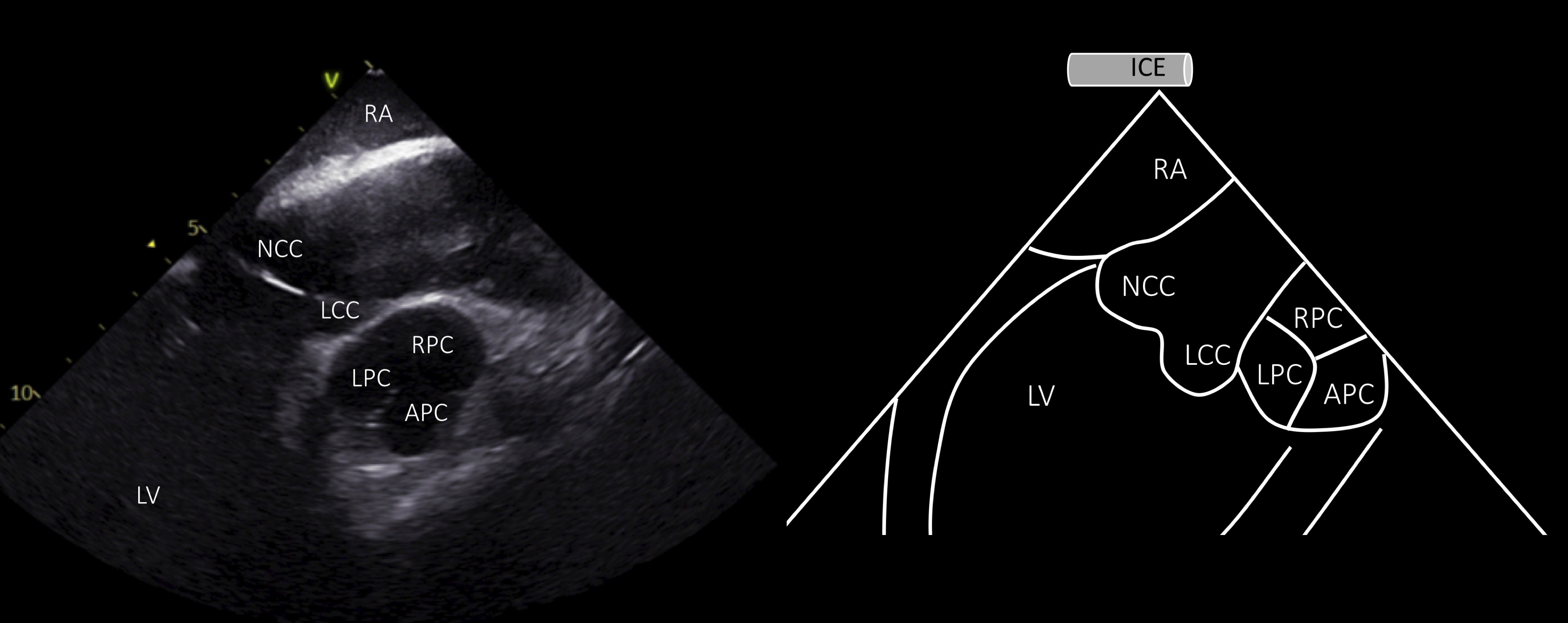 Fig. 6.
Visualization of the aortic and pulmonary valve from the RA. ICE view from the RA shows the aortic valve and ascending aorta in long axis and the pulmonary valve in short axis (ICE image at the left and schematic representation at the right side of the panel). RA, right atrium; LV, left ventricle; NCC, non coronary cusp; RCC, right coronary cusp; LCC, left coronary cusp; LPC, left pulmonary cusp; RPC, anterior pulmonary cusp; APC, anterior pulmonary cusp.
As above mentioned, clockwise rotation of the catheter brings the probe in the septal region of the RVOT where all the aortic cusps can be seen in short axis. Other structures that can be visualized from this view is the left main coronary artery, including left anterior descending (LAD) and left circumflex artery (LCx), the LAA and the left pulmonary veins (Fig. 5E–F). This view is important for catheter ablation of aortic cusps, as the precise position and stability of the ablation catheter can be assessed during mapping and deployment of ablation lesions.
The most common source of epicardial idiopathic VAs is the LV summit region. This area is the most superior portion of the left ventricular epicardium and has a triangular shape with its lateral sides formed by the left anterior descending and the left circumflex coronary arteries, while the base is bounded by a hypothetical arc connecting the two vessels at the level of the first septal perforating branch [17]. Catheter ablation of VAs arising from LV summit may be challenging because of the limited approach of the epicardial area, the proximity of the coronary arteries or the presence of an intramural origin of VAs. It is useful to map this region under ICE imaging and perform catheter ablation by adjacent structures such as the LCC, the subvalvular area (endocardial LVOT) and the RVOT (Fig. 7) [18].
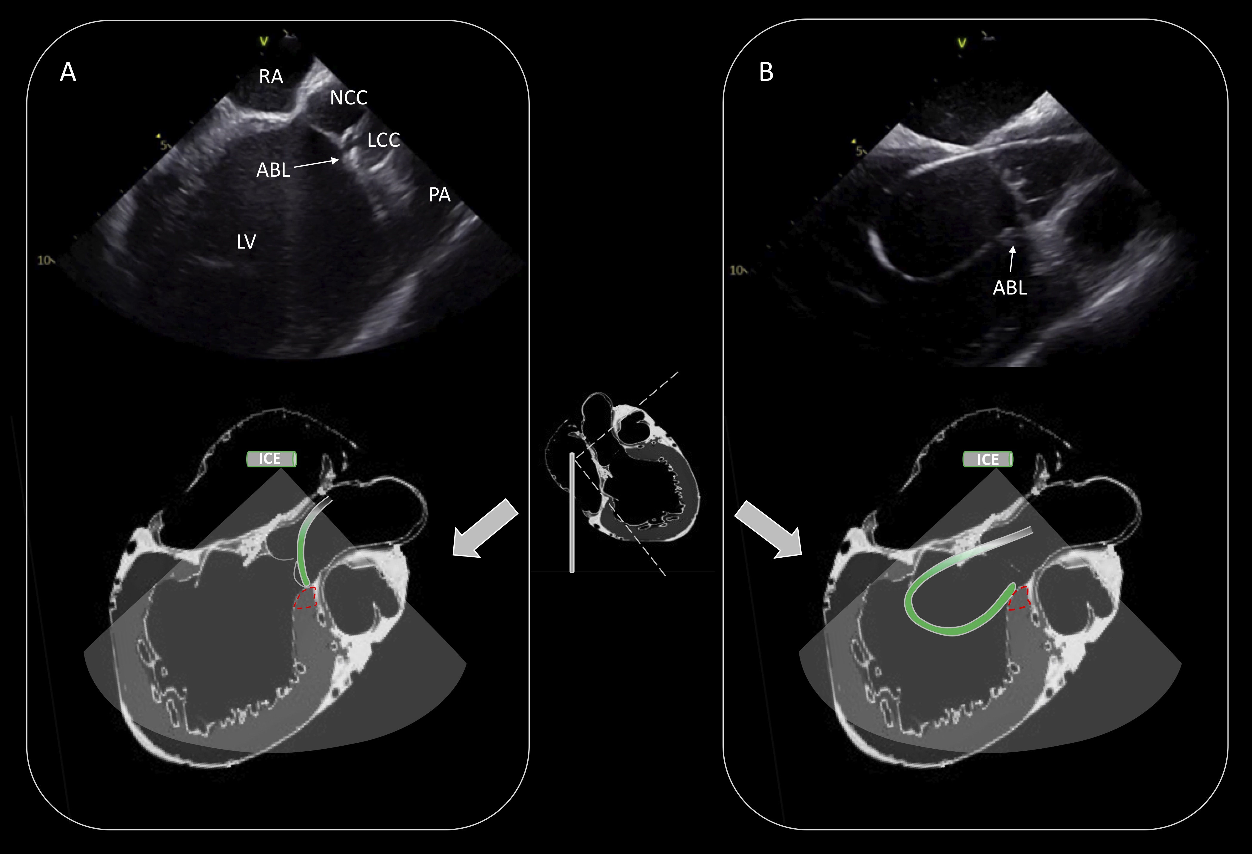 Fig. 7.
Ablation of PVCs originating from the LV summit. Activation mapping and ablation within the great cardiac vein/anterior interventricular vein was not technically feasible due to inability to advance the catheter in the distal coronary venous system. Effective ablation was achieved by adjacent sites (LCC: (A), endocardial LVOT: (B)). Schematic representation of the catheter position is shown in the lower part of the (A) and (B). RA, right atrium; NCC, non coronary cusp; LCC, left coronary cusp; PA, pulmonary artery; LV, left ventricle; ABL, ablation catheter; LVOT, left ventricular outflow tract.
Furthermore, real-time identification of the coronary arteries, during mapping
and catheter ablation of the coronary cusps, is crucial to prevent coronary
artery complications [19]. The LM coronary artery can be seen closely to LCC.
Slight modification of the position of the catheter with counterclockwise
rotation, can identify the course of the LM and its bifurcation to LAD and LCx
artery (Fig. 8). From the RA view, ICE can show the right coronary artery (RCA)
originating from the RCC in longitudinal view of the aorta. Accurate
identification of the coronary artery ostia enables ablation in the adjacent
areas while reducing significantly the risk of coronary injury, even without
performing coronary angiogram. A distance
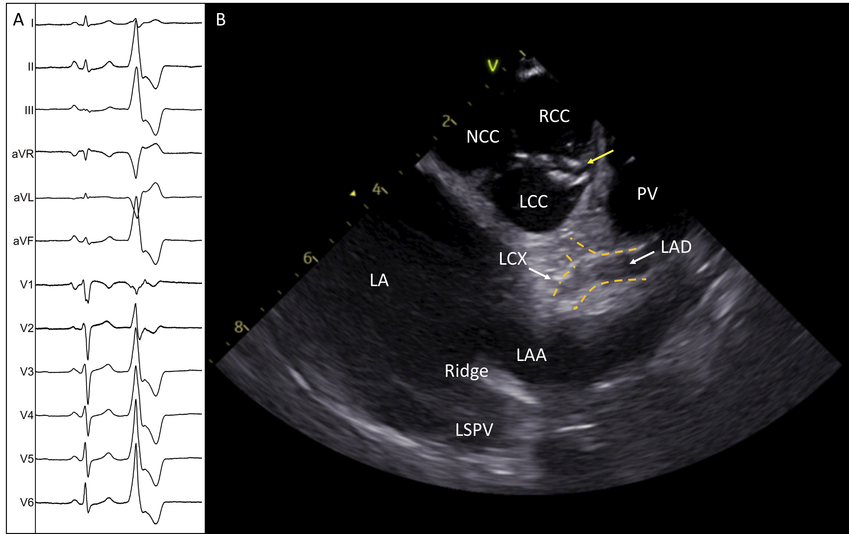 Fig. 8.
Successful ablation of idiopathic PVCs originating from the commissure of LCC-RCC. (A) Twelve-lead electrocardiogram shows the morphology of the PVC. (B) ICE image shows the aortic valve in short axis with the ablation catheter positioned in the commissure of L-RCC (yellow arrow). The image demonstrates the two main left coronary arteries and the safe distance of the ablation catheter. LA, left atrium; NCC, non coronary cusp; RCC, right coronary cusp; LCC, left coronary cusp; LAA, left atrial appendage; LAD, left anterior descending; LCX, left circumflex; ABL, ablation catheter.
From the RV view, once the aortic valve is seen in short axis, the subvalvular area of the RVOT and the PV can be identified in long axis after slight advancement and counterclockwise rotation of the catheter. The left pulmonary cusp (LPC) can be identified as the most leftward pulmonary cusp, adjacent to the aortic cusp, while the opposite is the anterior pulmonary cusp (Fig. 5F). Visualization of the precise location of the catheter in the distal RVOT is of great importance, as the pulmonary cusps may prevent the ablation catheter from achieving adequate contact with the RVOT, especially in the posterior wall. Furthermore, idiopathic VAs originating from the supravalvular region of the RVOT and the pulmonary cusps have been reported. ICE can be useful to place the catheter ablation above the cusp with U-curve maneuver when targeting suprapulmonary sites of PVC origins. In similar cases, the catheter is advanced beyond the PV and after applying curve it is pulled down and placed above the cusp. With this maneuver, the catheter is more stable and achieves better contact during catheter ablation. Visualization of the left coronary arteries is needed during deployment of RF lesions in this area to avoid inadvertent damage of the proximal LAD which courses in close proximity to the LPC.
Ventricular arrhythmias can arise from the PMs in the left ventricle. PMs are anatomically complex structures that represent challenging targets for catheter ablation. Stability of the ablation catheter during activation, pace mapping and lesion deployment is difficult in case of VAs originating from these endocavitary and mobile structures. Frequently, the source of origin of PM PVCs is located intramurally, thus requiring delivery of energy occasionally on both sides of the PM to eliminate PVCs. Without real-time imaging of the PMs, it is difficult to identify the exact location of the focus and ensure adequate contact of the tip catheter with the tissue. Real time ICE imaging facilitates assessment of the complex anatomy of the PMs, including the number and the shape of the heads and provides detailed representation of anatomical landmarks, improving the outcome of catheter ablation (Fig. 9) [8, 20].
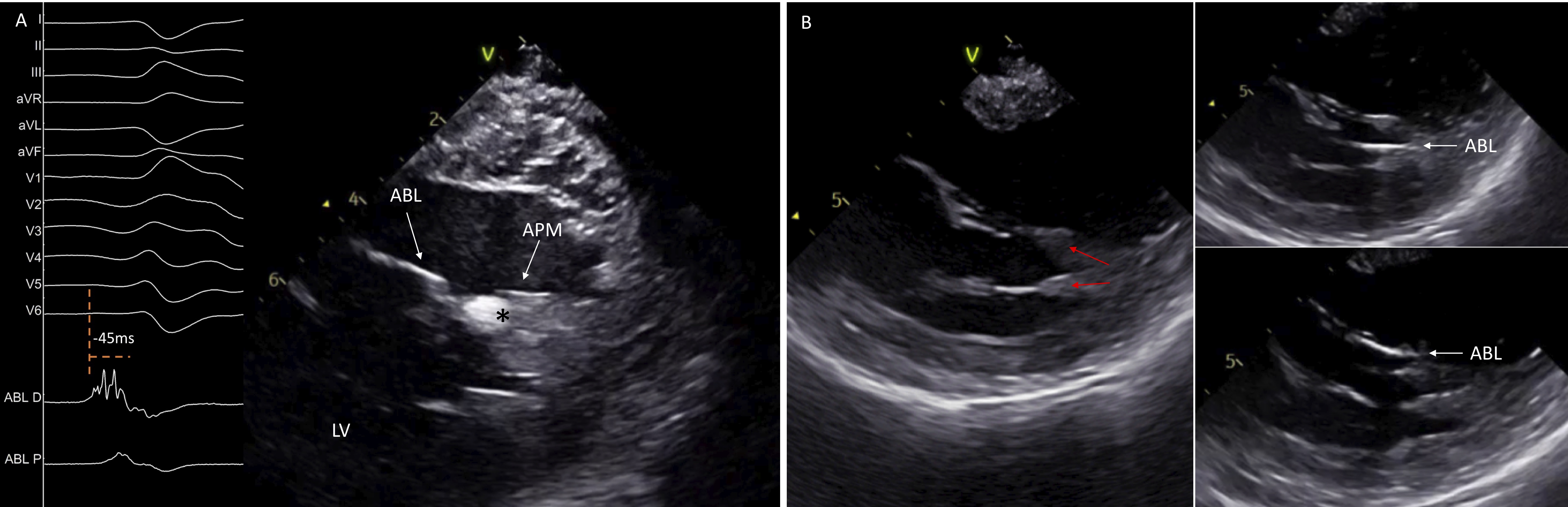 Fig. 9.
Catheter ablation of left ventricular papillary muscles arrhythmias. ICE image shows a single-headed APM with an echogenic area at its tip, corresponding at the site of origin of the premature ventricular contraction. Intracardiac electrograms display an early fragmented signal 45 ms pre-QRS on the ABL D (A). ICE identifies the presence of two separates heads of the APM and guides the ABL in its different sides (B). ABL, ablation catheter; APM, anterior papillary muscle; LV, left ventricle.
Apart from assessment of catheter-tissue contact, ICE can identify focal echogenic areas in the PM which may correspond to the site of origin of the arrhythmia (Fig. 9A) [21]. As described above, once the ICE catheter is placed into the RV, clockwise rotation will show the LV in long axis with the PPM displayed first, close to the posterior wall, while further rotation will show the APM. Therefore, posteromedial PM can be distinguished from the APM based on the distance of the base of the PM from the posterior wall. The posteromedial PM is in close proximity to the posterior wall, while the APM is always separate from the posterior wall.
The moderator band (MB) is a part of the septomarginal trabeculation, which connects the septum with the RV free wall and supports the APM of the right ventricle (Fig. 10) [22]. This structure can be the source of ventricular arrhythmias.
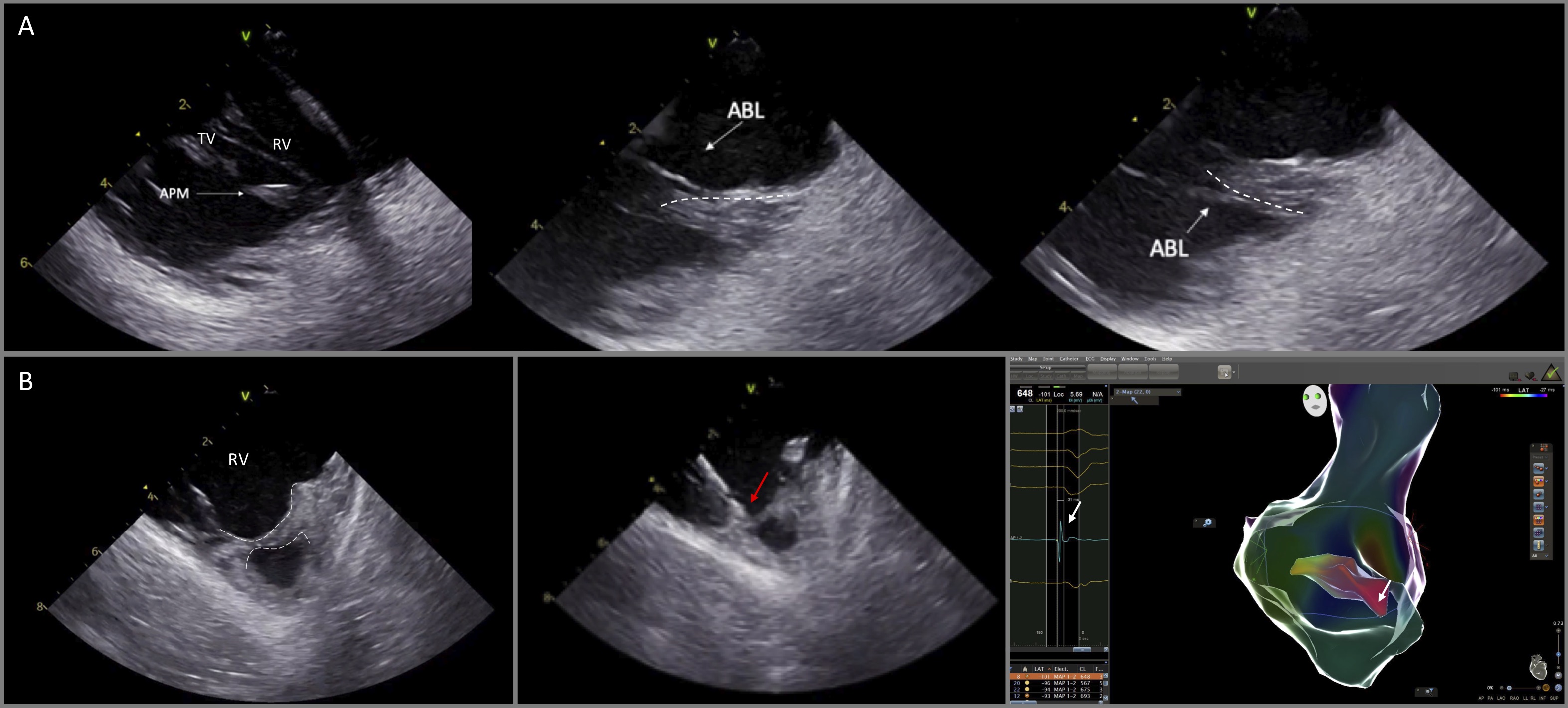 Fig. 10.
Catheter ablation of VAs originating from the anterior papillary muscle of the right ventricle and the moderator band. (A) ICE is particularly useful to delineate the anatomy and guide catheter manipulation to map and ablate from the superior and the inferior aspect of the papillary muscle (dashed lines). (B) (left) ICE image shows the moderator band (dashed lines). Ablation catheter (red arrow) was placed at the optimal site guided by ICE and electroanatomic mapping, recording the earliest activation time (white arrow, right panel) at the moderator band.
Visualization of these RV structures is feasible by advancing the ICE catheter into the RV and then releasing its curve with slight anteroflexion. Given the fact that the anatomy of the PMs and the MB is variable from patient to patient, gentle clockwise and/or counterclockwise rotation of the catheter should also be applied in order to identify all the length of the MB, such as the septal ventricular insertion and the connections with right ventricular PMs and the right free wall. As with the PMs of the left ventricle, PMs of the right ventricle and the moderator band are endocavitary mobile structures preventing catheter stability and effective ablation lesions. For optimal stability, the catheter should be placed parallel to endocardial surface of the right free wall, approaching the ventricular aspect of the MB [23].
Ventricular arrhythmias originating in the vicinity of the His bundle are not uncommon. Detailed activation and pace mapping of all the structures adjacent to the His area should be performed [24]. During mapping of the RV septum, ICE can be useful to assess catheter stability and to visualize structures, such as a prominent Eustachian valve and the leaflets of the tricuspid valve which may impede catheter manipulation in this area. Mapping of the anteroseptal area is achieved with the use a deflectable sheath. Downward deflection of the sheath and a reverse deflection of the ablation catheter result in an “S” figure of the sheath-catheter assembly that enables placement of the catheter behind the septal leaflet of the tricuspid valve with optimal catheter stability and reduced likelihood of inadvertent damage of the AV node during RF delivery (Fig. 11) [25].
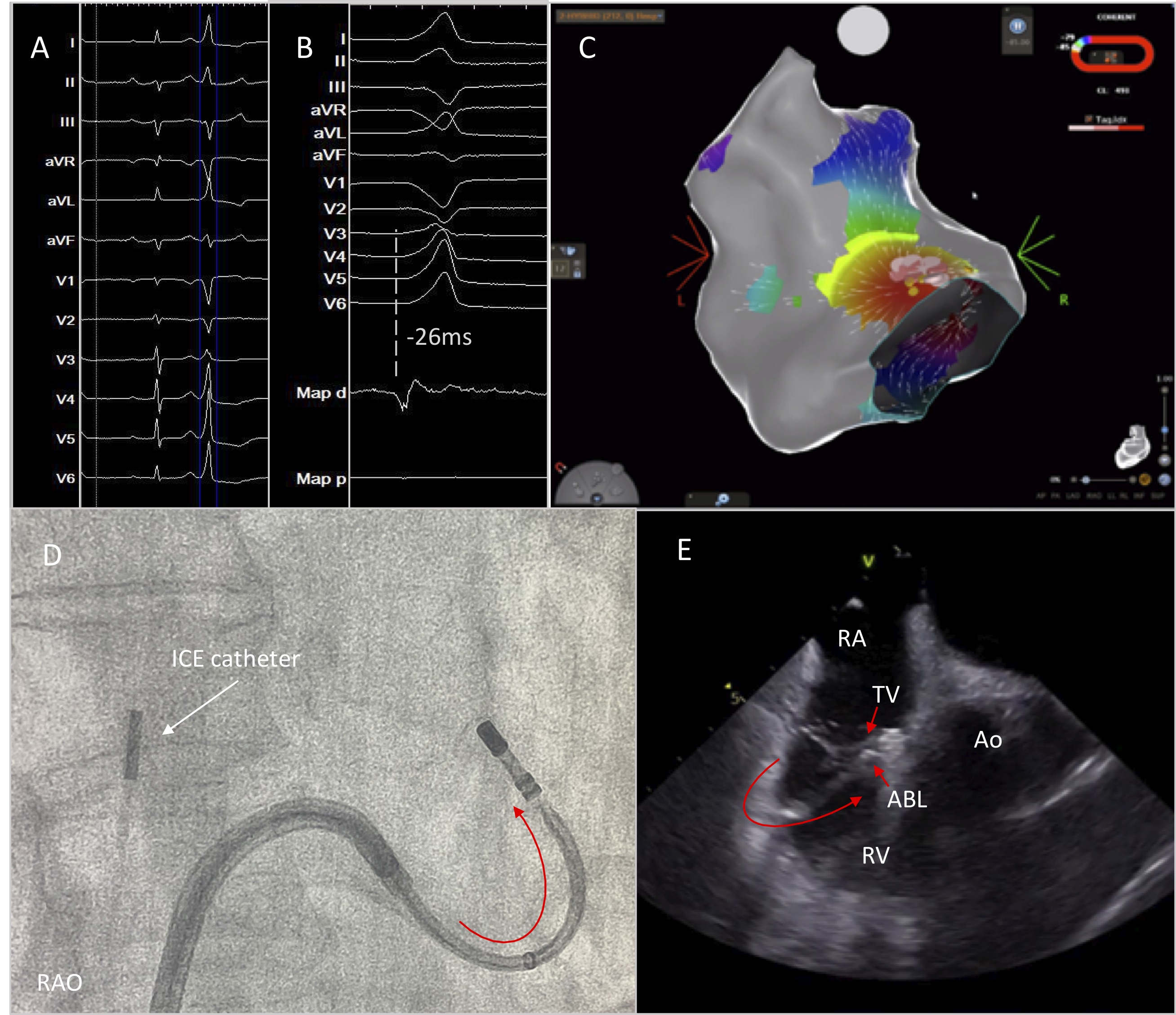 Fig. 11.
High burden of PVCs originating from the parahisian area. Successful PVC elimination was achieved by positioning the ablation catheter below the anterior leaflet of the tricuspid valve under continuous real time ICE imaging. (A) 12-lead ECG with the PVC. (B) Earliest activation at the Parahisian area. (C) Activation mapping using CARTO mapping system. (D,E) Optimal catheter placement behind the leaflet of the tricuspid valve by deflecting the sheath and the catheter in opposite directions for better stability. RAO, right anterior oblique; RA; right atrium; TV, tricuspid valve; ABL, ablation catheter; Ao, aortic valve; RV, right ventricle.
As both RCC and NCC are in close proximity with the His region, additional mapping of the aortic valve should be performed when RV activation mapping confirms prematurity at the Parhisian region [24]. The RCC is adjacent to the infundibular portion of the RVOT and the NCC is in close relationship to the interatrial septum. Detailed mapping in this region under ICE imaging is always helpful in order to focus on the posterior part of the RCC, which is in close relationship to the central fibrous body, the anterior part of the NCC which could be adjacent to the ventricular parahisian aspect and the NCC-RCC commissure [26, 27].
Use of ICE in catheter ablation of ventricular arrhythmias provides several advantages such as reduction of fluoroscopy time and dose, detailed imaging of cardiac structures and early detection of complications. Incorporation of this imaging modality in everyday practice should be promoted to improve procedural safety and efficacy during VT ablation procedures.
DA performed the literature review, drafted the manuscript and takes responsibility for the manuscript as a whole. TX reviewed the manuscript and revised it for any scientific and technical errors. ST contributed to the manuscript revision, validation and supervision.
Not applicable.
Not applicable.
This research received no external funding.
The authors declare no conflict of interest.